• Welcome to Overclockers Forums! Join us to reply in threads, receive reduced ads, and to customize your site experience!

BSEL mod FSB 1333

Overclockers is supported by our readers. When you click a link to make a purchase, we may earn a commission. Learn More.

Dawgdoc

Member
Joined
Feb 20, 2007
Heya all.

I tried the BSEL pad mod on my Q6600 last night, and am experiencing some issues.

Q6600 G0, P5K Premium with beta 0402 BIOS.

Performed the mod 3 times last nite with weird results. I am 100% positive the mod is in the correct place (couldnt get a good, non blurry pic) and I made absolutely certain that the inkwork was PERFECT. I would 'splash' some of the ink on a piece of paper, and then take a very fine needle to place small drops of ink on the CPU a small bit at a time. It turned out to be a very accurate way of placing the ink and no tape needed for an apparently perfect mod.

So here is what happened. Very similar situation all 3 times.

Computer boots and POSTS.

2 of 3 times, the FIRST POST after the mod showed a frequency of 2.68 (typically after a CPU 'change' or remount, my Q6600 shows 2.14 so I was initially optimistic).

2.68 appears to be FSB of 333 X 8

I had to F1 into BIOS due to the remount.....Everything was allready set on auto. FSB via the CPU BIOS screen shows 1066 though.... F10 out of BIOS and then boot to windows, and only shows 266 via CPU-Z.

This happened twice.

The final time, the INITIAL POST showed 3.00 frequency, which appears to be FSB 333 X 9. Same thing as previously with F1 mandatory BIOS after POST, F10 out of BIOS and everything stays at 266......

It appears as everything looks good since the very first post is FSB 333 (1333) each time, with 1 time the multi being 9, and twice the multi was 8....

It even seems proportional to my standard remount POST since....

2.68/2.14 = 1.25

333/266 = 1.25

ALSO at the 9 multi 3.00/2.40 = 1.25

Any ideas on what could be causing my mod to drop back to FSB 266/1066 after the initial boot?

I have seen posts where ppl have used this mod successfully on Q6600 before. Could it be the newest beta 0402 BIOS?

Something else?

Here are some screenshots from my last attempt which booted at 3.00.

Notice.....on my CPU BIOS screen it shows a frequency of 3.00, and it also shows an auto multi of 9. This means that my FSB COULD ONLY HAVE BEEN 333 (3000/9=333)

Then the next post after F10 out of BIOS is back to STOCK 2.4......

Any suggestions/advice appreciated!!
 

Attachments

  • 1st post after mod.jpg
    1st post after mod.jpg
    78.1 KB · Views: 25,327
  • BIOS after mod.jpg
    BIOS after mod.jpg
    53.9 KB · Views: 25,615
  • POST AFTER EXITING bios.jpg
    POST AFTER EXITING bios.jpg
    84.8 KB · Views: 24,527
  • cpuz after mod.jpg
    cpuz after mod.jpg
    40.5 KB · Views: 26,392
Here is where I placed the mod
 

Attachments

  • BSEL location.jpg
    BSEL location.jpg
    56.3 KB · Views: 35,104
Did you turn off SpeedStep, EIST, and all other "energy saving features"?
Speedstep and C1E are not a factor here, those lower the multi. If you look at the CPU-Z shot above, it shows a fsb of 266. That means that the mod was not successful ;)
 
Ink was a standard conductive ink pen.

"Circuitry Board" pen from radioshack.

Any other input appreciated. Id love to get this working and see if it opens up a little more OC room for me :)
 
have you reset the cmos or left the cmos batt out for about a hr, then tried to boot it up agian? bios may not be taking to well with the pad mod, could be because its a beta bios? just my best guesses on that since people with cheaper boards and only doing the 1066 mod havent had any issues.
Ink was a standard conductive ink pen.

"Circuitry Board" pen from radioshack.

Any other input appreciated. Id love to get this working and see if it opens up a little more OC room for me :)
is this the silver pen? if so you need to lightly scratch the thin clear part off. since its a mixure to where the exsposed silver has a clear coating when try. when the pens go to make contact they may not be going thru the clear coating.
 
i took a quick look at the data sheet for the q6600, by just connecting the VCC to BSEL2 to try and raise the low value to a high wont work.

id start over and try this. first wipe off all of the ink you currently have on there.

then try and put a small piece of electrical tape over bsel2... and put that in your mobo and see what happens.

if that doesnt work next thing i would try is to, keep the tape on there (assuming it covers the ENTIRE PAD of BSEL2) and draw a new trace from BSEL2 to the VCC pin like in the drawing you had above.

the reason why just connecting the 2 pins together without isolating BSEL2 wont work is because you cant simply raise an 0 aka low (grounded) value to 1 by running power to it, cus the power just gets grounded. so by placing the tape over the BSEL2 pin and then running a trace from the VCC power pin you make the mobo think that BSEL2 value is H aka 1.

but like i said i would first just try and put a piece of tape over it before drawing a trace.

hope that makes sense... if not questions are welcome :beer:
 
nd4: TY for the detailed info! Can you perhaps show me on a Q6600 BSEL diagram (i have one above) which spots you are referring to?

Im not exactly 100% sure, and want to be before I attempt anything else.

Also, any chance you can provide a link to your information about the Q6600? Ive looked but have not been able to find much of use.

Thx!

this is where i got the info the intel data sheet for the Q6000 series cpus

http://download.intel.com/design/processor/datashts/31559205.pdf

page 27 has the BSEL table

Page 40 has the pins on that im talking bout (TAKE NOTE thats a TOP VIEW)

let me take the pic you posted prior and do a lil magic in paint for ya

OK take a look at attached pic... that is the bottom of a standard socket 775 cpu... as stated in the pic you would need to put a piece of tape where the red square is, and then run a trace with your conductive ink from the top of the tape to the VCC pin specified.
 

Attachments

  • bselmod.JPG
    bselmod.JPG
    43.7 KB · Views: 27,936
Last edited:
TY for all of the help! Wow. Now thats detail :)

But....1 question, and herein may be my issue.

When looking at my diagram of where the mod was performed, it shows that this mod need be performed on the side OPPOSITE the gold triangle.

Your mod shows it on the same quadrant as the gold triangle.

So not only is the aforementioned mod that I performed missing the small bit of tape, but additionally it should be on a different quadrant?

oh crap hold up.... i think i got it wrong... i was looking at a top down view on intels site, this is a bottom view

DOH!
 
the FSB will never change from 1066, even when overclocked.
it reads the default, not the current.
9x 333 = 3 ghz, so its working on first boot.

as for why it doesnt hold after exiting bios.... I have no idea.
I've made a short list of the boards its worked on for me, but Asus Intel boards seem to be a different matter all together.
I've had very mixed results on Asus based, Intel boards.
meaning Intel Chipsets made by Asus.

sometimes it works... sometimes it barely works.
I have no idea why...

I took 1 CPU I knew had a working mod, out of a P5B deluxe that I killed, that the mod was working perfectly fine in.
but another P5B deluxe.... and the mod didnt work in that board.
I have no idea what happend, literally went from the same board to the same board... and in one it worked, in the next it didnt.
I have no solution for that...
 
I have a HP m8100y with Q6600. Tried for days to get a software overclock working to no avail (PLL is IDT CV190BPAG if anyone's interested)... finally I found a conductive pen and tried this mod as per Kunaak's instructions. No go. Booted at stock speed. Next I tried to cover BSEL2 with electrical tape. That worked! Didn't even have to draw the trace. Just ran OCCT for 30 mins with max temp at 58C on the stock HSF. Not bad. Thanks to everyone who posted, esp Kunaak and nd4spdbh2.
 
Works like a charm. I have the 2007 Intel Bundle. Q6600 paired with a DG33TL Intel Motherboard. I know having had a few Intel motherboards that over clocking would be near impossible. I have tried other things that outers have mentioned like SestFSB. Did not work no matter what. To many Lockups and crashes. So I started to read about the BSEL mods that people had started working on. I have read they they have worked for some but not others because of there motherboards and BIOS revs. I thought that I would try the above post to put a small piece of tape over the mentioned pin. When first boot I thought it had done nothing as he Intel BIOS sas that it is still running at the stock 2.4GHz and had a fsb speed of 1066. I took the processor back out of the case and looked over the tape and it looked to have a very good dimple in the tape. I decided to added another piece to make sure there was no connection. BIOS still says the default. When I booted into Windows I noticed that it was moving along a little faster. I launched CPUz and speed is now around 3.0GHZ and the fsb is 1333MHz. I was very happy. This is a wonderful mod for someone that does not want to purchase a new overclockable motherboard.
 
Works like a charm. I have the 2007 Intel Bundle. Q6600 paired with a DG33TL Intel Motherboard. I know having had a few Intel motherboards that over clocking would be near impossible. I have tried other things that outers have mentioned like SestFSB. Did not work no matter what. To many Lockups and crashes. So I started to read about the BSEL mods that people had started working on. I have read they they have worked for some but not others because of there motherboards and BIOS revs. I thought that I would try the above post to put a small piece of tape over the mentioned pin. When first boot I thought it had done nothing as he Intel BIOS sas that it is still running at the stock 2.4GHz and had a fsb speed of 1066. I took the processor back out of the case and looked over the tape and it looked to have a very good dimple in the tape. I decided to added another piece to make sure there was no connection. BIOS still says the default. When I booted into Windows I noticed that it was moving along a little faster. I launched CPUz and speed is now around 3.0GHZ and the fsb is 1333MHz. I was very happy. This is a wonderful mod for someone that does not want to purchase a new overclockable motherboard.

Two Points:

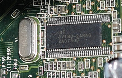
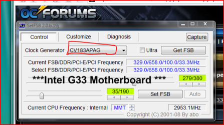
1) SetFSB *does* work on Intel G33 / Q6600. You use "CV183APAG" for the PLL chip. Even though my G33 shows "CV186-2APAG" on the PLL. I think the "183" PLL chip is used on the Intel 35 MoBo and that the "186" is a contemporary cousin so this works. I found this out by trial and error and let Abo know about it via email.

G33 PLL chip:

original.jpg

And using SetFSB:

original.jpg.png

I can hit about 3.05-3.1 GHz in this manner but for perfect stability I wind it back a bit.

2) Since SetFSB is software that turns the PLL chip to a higher speed by sending it the right message, you need to redo this all the time.

I'd like to do this Q6600 pin mod. But I read conflicting suggestions. One is that you cannot turn up the voltage on this ECU (and Intel G33 boards are pretty locked down BIOS wise...which is why I am using SetFSB). Set FSB also gets my memory up to 985 Mhz since that is affected by the FSB frequency too. So:

2A) Can the Q6600 voltage be tweaked upwards to potentially gain more overclock via pinmods? If so how. Thanks.

2B) To do the FSB mod to hit 1333 do I connect those two pads, insulate the one in between them, or insulate the lowermost and then pen in like in the pic over the insulation?

Once having achieved the 1333 what will my DDR2 800 memory see? I can use SetFSB on top of this I suppose. But I want to get fast ECU and Fast memory results.

Thanks for your time and suggestions.
 
Last edited:
I'm almost positive you can do some kind of pad mod to alter the VID of the chip. This would tell the MoBo to send the chip more voltage. I don't know the layout, but hopefully someone can chime in w/ the the VID codes, and what needs to be changed.

I think you're supposed to just cover the one pad w/ tape. I haven't done the mod yet, but I've been reading the threads. I've considered doing it to see if I can get a higher max FSB speed out of this quad.

I'd guess that after the mod your MoBo would automatically set the RAM to 800, but you'd be at a 333FSB, so you'd be running a different memory divider. You were on the 2:3 divider before, and I think you'll end up on the 5:6 divider after. If you managed to somehow use SetFSB to crank the FSB up to 400 from there then your RAM would be at 960MHz. Whatever speed you end up on the RAM you could always use memset to tweak your RAM timings and that might give you the same or even more performance than running at a faster speed.
 
you will have to adjust the ram divider when you do the pin mod. the Q6600 should do 333fsb with just 1.35volts... what is the cpu getting now? the pad mod is a more secure way to have the pcie/pci speeds locked.

its still on pad but its the VID pads... you can find that stuff in intel white papers..

Well the ram divider will have to adjust itself as Intel BIOS is locked down. It ran 5:4 with 667 memory and changed itself to 12:8 for the new 800 memory to hit 800 Mhz.

The CPU is getting the stock ~1.25 volts (which seems to drop to somewhere around 1.15 when idling due to speedstep).

Using SetFSB and the old 667 Memory I could hit about 3.1 GHz with a Big Typhoon keeping Loaded temps in the high 40s low 50s.

I have not tried maxing out SetFSB with the new DDR2 800 memory as I just loaded it in. I am wondering if I can hit the same figure or not...that would put my memory @ 1035 Mhz and stock 1.8 voltage. It might not do that. But it does about 985 just fine on 1.8 volts.

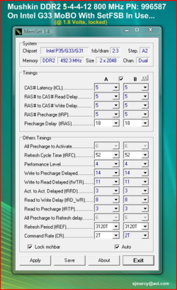
Here are the timings that popped out in memset...this is nominally 5-4-4-12 1.8 volt memory DDR2 800...any suggestions?:

original.jpg.png

Doing Everest Photoworxx which is relevant to my photography efforts:

original.jpg
 
Last edited:
Back