• Welcome to Overclockers Forums! Join us to reply in threads, receive reduced ads, and to customize your site experience!

EE Help Needed: Motherboard tray docking circuit

Overclockers is supported by our readers. When you click a link to make a purchase, we may earn a commission. Learn More.

Captain Slug

Helpful Senior Member
Joined
May 23, 2001
Location
Asteroid B-612
I am working on a project that has one particular requirement that is beyond my expertise.

These pictures explain what I need fairly well
mk6_d_1.jpg
mk6_d_4.jpg

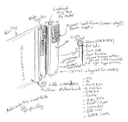
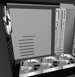
Essentially I will be needing two PCBs (2"x12" in size) that will act as a pass-through connector allowing all of the cables from the various parts of the machine to connect in a central location and then interface with the motherboard tray through a second PCB. The two will connect together (using typical sized pins used for motherboard headers) when the tray is inserted.
If there ends up being enough space left over an intergrated fan controller would also be extremely useful. Since the circuit is also extending the power/reset switches and LCD indication from the motherboard a front panel PCB may also be required (8" x 1" in size).

I am more than willing to pay for this to be designed and made and I would appreciate any thought, comments, questions, etc.

A theoretical requirement that I am not quite sure how to implement would be a locking mechanism that when the machine is powered-on will not allow the PCBs to be disconnected. I would love to hear any ideas on how to accomplish this.

mk6_d_5.jpg

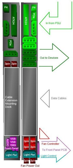
The upper section contains all of the power connectors and except for a few power traces to feed the light power output and fan controller it's an independent unit and can have it's own type of interconnect capable of handling the required current load. Whatever interconnect is used the pin requirement is only around 50 for this layout.

The middle section will just be a series of precisely positioned threaded mounting holes for attaching the flush-mount cable extensions (on the motherboard side) and the flush-mount rounded IDE and SATA cables (on the case side). This section will require custom cables, but no actual circuitry.

The lower section serves 3 functions.
1. Front-Panel extensions (Power/Reset, LEDs, USB2.0, Front Audio, 9-pin Serial header)
2. Light control (2 switches that toggle the 4-pin connectors)
3. Fan controller (on the Front-Panel PCB itself)

The front panel PCB will contain all the switches, ports, and fan controlling electronics. It can connect to the Plug-Bus with one or two cables. It's size limit is 8x2 inches.
The serial header extension is meant as a pass-through for an LCD unit. This could either be a header on the plug-bus, or an actual DB9 connector.
 
Seems like an interesting project. Regarding the 2 12x2 boards adjacent to the mobo. Why not make one PCB instead. It would be a much neater design, and the extra real-estate would help with the ATX plug traces. E-mail me a detailed layout of exactly what you want done. I use PADS and WinBoard for schematics, so a fan controller is also possible.
 
If it were me tackling this project, i'd use an edgeboard connector system for at least the power. it seems to work great in the rackmount case's PSU i have, although the load might be a little more with your needs. i can grab some pics if needed.

Then I'd put matching sockets on each side and use jumpers, to go from one ATX plug ot the one on the mobo. then same with all the switches, SATA, IDE, USB, LEDs and switches. then you could use IDE cable (s) to connect the front panel to the case mounted board. I'd put the socket for the edge connector on the case side.

i'm guesing this is for some sweet mobo tray type thing?

and i noticed you changed your av.. is it like the first time in 3 years?
 
noxqzs said:
Why not make one PCB instead.
I need something to act as an interface to allow the removal of the motherboard tray without having to unplug any cables. I'm not just trying to centralize cable connections, but rather make the entire motherboard tray a modular unit. If you need to increase the size of either PCB or can think of a better way to do this by all means let me know.

The 3D conceptual image is how I want the layout of the connectors setup, and the upper and lower halves of the plug-bus are almost entirely independent. The only traces connecting the two would be the power connections for the fans and lights on the lower half.
I do however need some expert advice on what interconnects to use for connecting the two PCB halves. I was thinking that a mixture of barrel connectors and D-subs would work fine depending on what the voltage requirements for a certain connection will be. Edge connectors were also discussed, but could become more difficult to implement.

If you need me to I'll try to work up a more detail schematic, but if you understand what is I'm working towards I would seriously appreciate your input or any practical design work you can come up with.

four4875 said:
If it were me tackling this project, i'd use an edgeboard connector system for at least the power. it seems to work great in the rackmount case's PSU i have, although the load might be a little more with your needs. i can grab some pics if needed.
And edge connector would work for the majority of the connections, I'm a little wary of using them when the requirement for the 12V connections are around 5A though. I was thinking that most of the lower voltage connections could be consolidated into a 50P D-sub connector.

four4875 said:
Then I'd put matching sockets on each side and use jumpers, to go from one ATX plug ot the one on the mobo. then same with all the switches...
Yes, the plan is for the motherboard tray half of the plug-bus to connect to the motherboard with short interface cables. The data cables however will just be cable extensions surface-mounted onto the plug-bus. That was decided early on as the best way to reduce potential resistance of the device.

The end goal is to have a modular motherboard tray which can be removed without having to detach any cables.

four4875 said:
and i noticed you changed your av.. is it like the first time in 3 years?
I change it once a year, but it's been bomberman in one form or another for the past 3 years.
 
Last edited:
Why not use two 24pin atx connectors to interafce the power together instead of the indvidual connectors when going in from PSU. that would make docking alittle simpler.

Next for your locking device you could try an elctromagnet.

Finally for a good connector to put it all together i'll look at the Mouser catalog tonite
 
Ok. just so I understand right. You want a MOBO tray, that is removable. On this tray you want one PCB interface board, with connectors to the motherboard. In addition, you want a master bus of some sorts to interface with the PCB mounted in the case. The PCB within the case has all the interfaces for components, front panel, fan controller, etc...


I have a few ideas how to handle the power. Do you want to integrate data into the PCB, and which type, parallel or serial?
 
noxqzs said:
Ok. just so I understand right. You want a MOBO tray, that is removable. On this tray you want one PCB interface board, with connectors to the motherboard. In addition, you want a master bus of some sorts to interface with the PCB mounted in the case. The PCB within the case has all the interfaces for components, front panel, fan controller, etc...
Exactly
noxqzs said:
I have a few ideas how to handle the power.
Do tell.
noxqzs said:
Do you want to integrate data into the PCB, and which type, parallel or serial?
After alot of discussion with some other individuals it was mentioned several times that the added resistance of trying to integrate the data cables (especially SATA) would lead to data loss, so I revised to design so that the PSB halves DO NOT bridge those connections. This saves PCB space, and significantly reduces the pin requirements.

The data cables will simply connect to the motherboard via an extension cable. Then both cable connector halves will screw-mount onto the PCB (or an enclosure over the PCB) to facilitate the connection and seperation of those cables with the rest of the motherboard tray.
 
That's a great idea. I wish I could help you, but my knowledge in this area isn't too great. But I thought I'd let you know that this is the best idea I have seen in a long time.
 
without IDE and the likes, it gets MUCH easier. i think edge connectors are the way to go, nice and easy to keep lined up and nice contact. they can be nice and wide to accomodate higher loads and all, it seems to work fine for the rackmount PSUs that are slide out like. i might be able to start workin on a PCB layout or similar, but basically dont hold your breath, i have ADD and will lose motivation and get distracted VERY quickly, so it might get started for like a couple hours then ill be outside burning the neighbors cat (joking on the cat burning)
 
If you didn't mind going in the 3rd dimension, and stacked PCBs, that would solve alot of issues. I just did a small test with a 30 inch ATA extension, and drives still worked. A small bridge like you want to implement shouldn't cause a problem for this, especially for serial which has much higher tolerances.

And while you are on the subject of connectors. Stick with the norm, and get the standard MOLEX ones used on the MOBO and components. It will make the design much easier to digest.
 
noxqzs said:
If you didn't mind going in the 3rd dimension, and stacked PCBs, that would solve alot of issues.
Stacked PCBs will be fine and understandably would make routing traces to spec much easier. If there are any other space saving measure you can think of just post them.
noxqzs said:
And while you are on the subject of connectors. Stick with the norm, and get the standard MOLEX ones used on the MOBO and components. It will make the design much easier to digest.
If you're talking about molex connectors for the interconnect, those might work but how much force would be required to insert/remove 50 ATX pins at the same time?
noxqzs said:
I just did a small test with a 30 inch ATA extension, and drives still worked. A small bridge like you want to implement shouldn't cause a problem for this, especially for serial which has much higher tolerances.
If you can get the Data cables added without any problems that would be spectacular. From what I've been research Serial ATA has some issues and limitations concerning resistance affecting its signals.

And if you can, please make the mounting holes for the PCBs at the standard ATX spacings so that this can be mounted on the eATX stand-off holes.


I'm more than willing to compensate you for your time, parts, etc if you can help me make a finished usable part. And once we're both sure it works maybe I could even make a duplicate case (that this PSB will be a central part of) for you at cost.

Edit: I would also like to see a locking mechanism if possible. It's not essential but it's a feature I would like to eventually see as a fail-safe. It would also make the device more fool-proof. :beer:

I DON'T REALLY HAVE A TIME-TABLE FOR THIS but I'm hoping to have something that works sometime before or around December so I can start work on the project that this part is designed around.
 
Last edited:
for a locking mechanism... so something to use a double action selenoid, so when power is applied it snaps it shut, when released it reverses. only problem i see is getting it to shut off after latching. maybe it would be easier for a mechanical latch, which has a switch to break the pin14 connection from the psu when not latched, so if unlatched it shuts off? a selenoid of sorts seems easiest, but getting it to open when power is turned off.... unless you can find one that will handle constant power while the comp is running withough heating up and melting..... pic coming in a few.

it works as... the selenoid has power, so it keeps pushing the latch shut. let off power, spring pulls it open, and it can slide apart. not too complicated.
 

Attachments

  • latch.JPG
    latch.JPG
    11.4 KB · Views: 599
Last edited:
a question.... how many connections will you need for front panel switches, LEDs, sound, USB... all that, so we can start gettin ideas for connectors to use. im thinking like the kind used in removable hard drive trays might work, and the plug parallel printers have (not the D sub, the other one)

is there anything keeping the boards from mounting with their larg faces parallel to each other? they could then mount to the board with angle steel or whatever. then it could expand the possibilities for connector arangment.

I'm thinking towards a layout that anyone could put together, not having to have some fancy special lab put the multiple layers of PCB together and all, just a gut with components and a soldering iron (After the board is made that is) this sounds like a really fun project.
 
four4875 said:
it works as... the selenoid has power, so it keeps pushing the latch shut.
Most spring return solenoids, especially if their current load is limited, should work fine as a pin-through-tab lock rather than a latch mechanism.

four4875 said:
a question.... how many connections will you need for front panel switches, LEDs, sound, USB... all that, so we can start gettin ideas for connectors to use. im thinking like the kind used in removable hard drive trays might work, and the plug parallel printers have (not the D sub, the other one)
Front Panel output
2 x USB 2.0 = 8 pins
Audio FPC (One Headphone, one Mic) = 6 pins
Reset = 2 pins
Power = 2 pins
LEDs x2 = 4 pins
Light toggle switch = 2 pins

Total = 24

Optional additions (if space allows)
Another Light toggle switch = 2 pins
1 x Firewire = 8 pins

Sub Total = 34

The fan controller would be independent from the rest of the PCB and would receive power from one of the case-side plug-bus molex connectors, then output power to the lower 3-pin connectors on the plug-bus. Doing it this way keeps the front-panel cable and plug a low voltage path with more connector options.
is there anything keeping the boards from mounting with their larg faces parallel to each other? they could then mount to the board with angle steel or whatever. then it could expand the possibilities for connector arangment.
If there's an easier way for this to be made that still allows for durability and a general consolidation of wires I'm all for it. Another potential solution would be to have all the molex connectors installed as 90-degree plugs off one edge of the board, then have the two boards connect together with a simple pin header array.

I'm thinking towards a layout that anyone could put together, not having to have some fancy special lab put the multiple layers of PCB together and all, just a gut with components and a soldering iron (After the board is made that is) this sounds like a really fun project.
I was just thinking PCBs would save space and be easier to mass-produce. I'm sure something like this could be made with ALOT of wire and solder, but I wouldn't trust that kind of solution with anything other than power (which is what I was leaning towards). The remaining issue them would be trying to keep the enclosure small, but still functional.
 
Last edited:
i was getting at that single layer PCBs are much easier to etch and drill and all, most of the members here could build one if they set their minds to it. but multi layered are scary, so i'd stay away form them lol.

I was thinkin of some of the connectors like on old vid cards.. how they had RAM addon boards... if you know what im talkin about... like larger versionas of those or something. also might consider the plugs used in laptop docking stations, with the pins to line them up and all.
 
captain, i have the PSU out of the rackmount, ill try to get pics tonight hopefully, before i elave for columbus. if not ill have pics for ya on sunday, hpefully they'll help a little.
 
four4875 said:
i was getting at that single layer PCBs are much easier to etch and drill and all, most of the members here could build one if they set their minds to it. but multi layered are scary, so i'd stay away form them lol.

I think you misunderstood what I meant. I was thinking of single-layer pcb's that are mounted on top of each other, with spacers in between.

I managed to locate 80-pin connectors you could use for data. They look something like the ones I used in my samples. They make 90*female ones, so putting boards side by side is no problem. They make larger versions for higher capacity. The ones in the pics would be good for data or < 3A. With all the leverage you would have with the mobo tray, insertion force would be negligeble. Work permitting, I can spend some time on it this weekend.

opto01.jpg

opto02.jpg
 
After my first try I've basically started the PCB design over from scratch because of my previous inability to take into consideration the peak current load requirements of certain traces. In deciding upon different connectors and consolidating some portions of the PCB for better trace connections I've managed to turn this into a fairly simple single-sided PCB.
Here's the new schematic: http://www.captainslug.com/modding/mk6_plug-bus_th_pcb2.gif

The two halves will connect through 1 DB15 and 2 DB37 90-deg connectors.

The other half is going to take more time to design and will need to be double-sided.

The data cables are no longer included because I can simply use an array of these mounted on-top of the fairly blank portion of the PCB.
221005A.jpg


I haven't made any head-way on finding a workable latching mechanism but hopefully I can discuss this further with the local electrical engineer I finally found.
 
Last edited:
Back