- Joined
- Oct 12, 2001
- Location
- Los Angeles
Retired Sticky
I will attempt to do a thorough guide to make this mod as easy as possible!
A BIG thanks to PMM for discovering where/how to mod the VDD on THIS board!!!
*You can ruin your board attempting this mod! I take NO responsibility if you do!
Here is a list of things you will need:
1. Soldering iron and solder
2. Hot Glue gun (optional but highly recommended!)
3. 1M ohm FIXED resistor found here
4. 1M ohm potentiometer (VR) found here
5. Wire - any kind will do, I used some old fan wire.
6. Thermal tape or just double sided will work.
7. Digital multimeter
Before you even touch the board, follow these instructions:
1. The 1M ohm potentiometer has THREE (3) solder points, we will use the CENTER point and EITHER of the other 2, it does not matter.
2. Solder the wire to one end of the 1M ohm FIXED resistor, I cut one end of the resistor short for this.
3. Solder the same wire to any of the 3 points on the potentiometer EXCEPT the center point.
4. Now we need a ground wire that will be soldered to the CENTER post of the potentiometer.
-----> At this point you should have the Fixed resistor soldered to a wire which is then soldered to one of the OUTER pins of the potentiometer. You should now also have a separate wire soldered to the CENTER pin of the potentiometer.
-----> TIP - An easy way to ground WITHOUT having to solder to the MOBO is to use an old 3 pin fan connector that plugs into one of the fan headers on the MOBO. If you use this, the BACK wire is the one for ground in the plug, the other wires can be cut off. If you don't have a 3 pin connector, no worries, you can solder the end of the ground wire to the ground pin on one of the fan headers OR, around one of the mobo mounting screw holes.
Now onto the board we go!
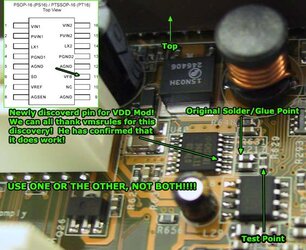
***UPDATE! Thanks to vmsrules, he has discoverd an ALTERNATE pin on the mobo to solder to! Use either this new one, or the old one but NOT BOTH! Everything else in the mod REMAINS the same.
Here is a pic showing the NEW PIN:

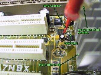
And my JUST finnished VDD mod to my NEW board using SMD Grabbers! No soldering!!!! Check it out! Works like a dream!

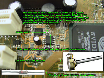
Take hold of the 1M ohm FIXED resistor and obviously use the side that does not have the wire soldered to it! I strongly recommend using a hot glue gun to affix the fixed resistor to the point on the board - You can solder it too if you wish but this should be reserved for people with excellent soldering skills! The point is VERY small and the resistor is VERY sensitive to heat, if you touch the resistor with the iron, the board will be borked!
While holding the fixed resistor to the point on the board, use the hot glue gun to get some glue around the area to securely hold the resistor in place. BE CAREFUL NOT to cover the VDD voltage test point with the glue!!!!! Look carefully at the picture. If you cover the test point, you can not test the VDD voltage! It is OK to get glue anywhere else, it will not harm the board. I would hold the connection for about 2 to 3 minutes while the glue dries. Be careful not to violently move the connection.

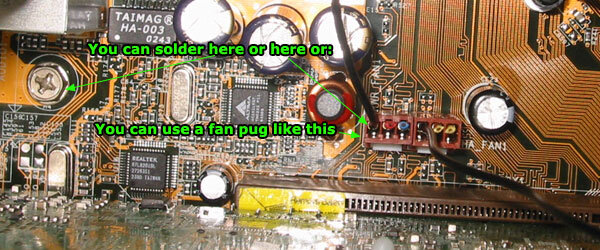
Once this is all done, there is only 1 thing left to do, ground the connection to the motherboard. Take the wire on the center post of the potentiometer and either use a fan plug like described above or solder the wire to the GROUND pin of a fan header or around any mounting hole of the mobo. Make sure you KNOW which fan pin in the header is ground, this picture should help:

What I did was I took some thermal tape which is double sided, you can use any double sided tape really, and taped it to the bottom of the potentiometer. I then stuck it on a nearby resistor so that it doesn't 'hang' off the board. Just don't tape it to the Southbridge!
Picture courtesy of impulse: PLEASE NOTE that in this picture, impulse soldered the connection, I suggest to use the glue method. This is here for reference.

Before you fire up your machine, get the potentiometer into the center position, doesn't have to be exact. With this setup, with the VR turned all the way one way you should get around 1.71V and with it turned all the way the other way you should get around 1.91V. Once you fire the rig up, get your multimeter out and test the voltage reading at the reading point. Turn the VR slowly one way, does the voltage go up or down? I have mine set to 1.85V and that is as high as I am comfortable with.
If you would like to see my board with VDD, VCORE and VDIMM mods click this link: http://www.netbetty.com/H20/asus/wholeboard.jpg
I will attempt to do a thorough guide to make this mod as easy as possible!
A BIG thanks to PMM for discovering where/how to mod the VDD on THIS board!!!
*You can ruin your board attempting this mod! I take NO responsibility if you do!
Here is a list of things you will need:
1. Soldering iron and solder
2. Hot Glue gun (optional but highly recommended!)
3. 1M ohm FIXED resistor found here
4. 1M ohm potentiometer (VR) found here
5. Wire - any kind will do, I used some old fan wire.
6. Thermal tape or just double sided will work.
7. Digital multimeter
Before you even touch the board, follow these instructions:
1. The 1M ohm potentiometer has THREE (3) solder points, we will use the CENTER point and EITHER of the other 2, it does not matter.
2. Solder the wire to one end of the 1M ohm FIXED resistor, I cut one end of the resistor short for this.
3. Solder the same wire to any of the 3 points on the potentiometer EXCEPT the center point.
4. Now we need a ground wire that will be soldered to the CENTER post of the potentiometer.
-----> At this point you should have the Fixed resistor soldered to a wire which is then soldered to one of the OUTER pins of the potentiometer. You should now also have a separate wire soldered to the CENTER pin of the potentiometer.
-----> TIP - An easy way to ground WITHOUT having to solder to the MOBO is to use an old 3 pin fan connector that plugs into one of the fan headers on the MOBO. If you use this, the BACK wire is the one for ground in the plug, the other wires can be cut off. If you don't have a 3 pin connector, no worries, you can solder the end of the ground wire to the ground pin on one of the fan headers OR, around one of the mobo mounting screw holes.
Now onto the board we go!
***UPDATE! Thanks to vmsrules, he has discoverd an ALTERNATE pin on the mobo to solder to! Use either this new one, or the old one but NOT BOTH! Everything else in the mod REMAINS the same.
Here is a pic showing the NEW PIN:
And my JUST finnished VDD mod to my NEW board using SMD Grabbers! No soldering!!!! Check it out! Works like a dream!
Take hold of the 1M ohm FIXED resistor and obviously use the side that does not have the wire soldered to it! I strongly recommend using a hot glue gun to affix the fixed resistor to the point on the board - You can solder it too if you wish but this should be reserved for people with excellent soldering skills! The point is VERY small and the resistor is VERY sensitive to heat, if you touch the resistor with the iron, the board will be borked!
While holding the fixed resistor to the point on the board, use the hot glue gun to get some glue around the area to securely hold the resistor in place. BE CAREFUL NOT to cover the VDD voltage test point with the glue!!!!! Look carefully at the picture. If you cover the test point, you can not test the VDD voltage! It is OK to get glue anywhere else, it will not harm the board. I would hold the connection for about 2 to 3 minutes while the glue dries. Be careful not to violently move the connection.
Once this is all done, there is only 1 thing left to do, ground the connection to the motherboard. Take the wire on the center post of the potentiometer and either use a fan plug like described above or solder the wire to the GROUND pin of a fan header or around any mounting hole of the mobo. Make sure you KNOW which fan pin in the header is ground, this picture should help:
What I did was I took some thermal tape which is double sided, you can use any double sided tape really, and taped it to the bottom of the potentiometer. I then stuck it on a nearby resistor so that it doesn't 'hang' off the board. Just don't tape it to the Southbridge!
Picture courtesy of impulse: PLEASE NOTE that in this picture, impulse soldered the connection, I suggest to use the glue method. This is here for reference.
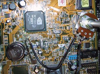
Before you fire up your machine, get the potentiometer into the center position, doesn't have to be exact. With this setup, with the VR turned all the way one way you should get around 1.71V and with it turned all the way the other way you should get around 1.91V. Once you fire the rig up, get your multimeter out and test the voltage reading at the reading point. Turn the VR slowly one way, does the voltage go up or down? I have mine set to 1.85V and that is as high as I am comfortable with.
If you would like to see my board with VDD, VCORE and VDIMM mods click this link: http://www.netbetty.com/H20/asus/wholeboard.jpg
Last edited by a moderator: